Biochemical, Gene Regulatory Networks Modeling with GUI
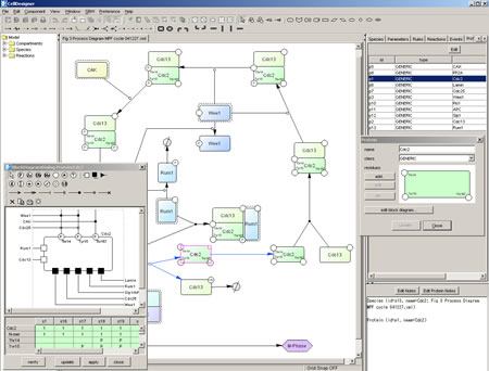
CellDesigner is a structured diagram editor for drawing gene-regulatory and biochemical networks. Intuitive user-interface helps you to draw a diagram in rich graphical representation with your own design.
Visual Representation of Biochemical Semantics
Networks are drawn based on the process diagram, with graphical notation system proposed by Kitano.
The Process Diagram
The Process Diagram is a state transition diagram.
In the process diagram representation, each node represents state of molecule and complex. Arrows represents state transition among states of
molecule. In the conventional diagrams, arrow generally means “activation”
of the molecule. However, it confuses semantic of the diagram as well as
limiting possible molecular processes that can be represented.
 For example,
a process of MPF factor activation in cell cycle, kinase such as Wee1
phosphorylates residues of Cdc2 that is one of components for MPF (left).
However, MPF is not yet activated by this phosphorylation. If we use “arrow” for activation, we cannot properly represent such an interaction.
For example,
a process of MPF factor activation in cell cycle, kinase such as Wee1
phosphorylates residues of Cdc2 that is one of components for MPF (left).
However, MPF is not yet activated by this phosphorylation. If we use “arrow” for activation, we cannot properly represent such an interaction.
In the process diagram, whether a molecule is “active” or not is represented as a state of the note, instead of “arrow” symbol for activation. Promoting and inhibition of catalysis are represented as modifier of state transition using a circle-headed line and a bar-headed line, respectively.
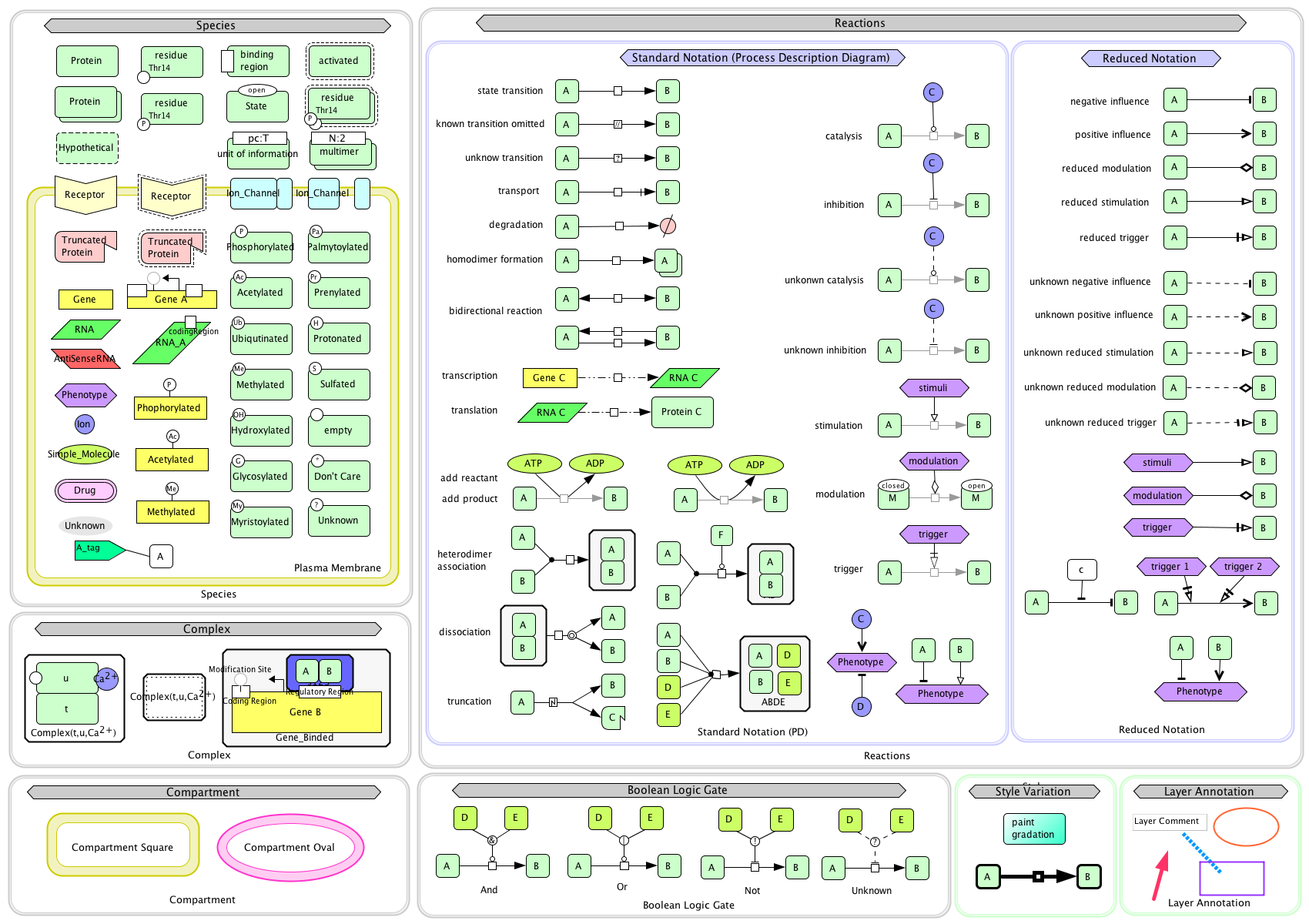
CellDesigner supports graphical notation and listing of the symbols based on proposal by Kitano and adopting the most of SBGN (=Systeme Biology Graphical Notation) Process Diagram Level 1 notations..
- Kitano, H.et al. "Using process diagram for the graphical representation of biological networks", Nature Biotechnology 23(8), 961-966 (2005)
- Kitano, H.. "The Process Diagram: Rational and Definition" - [ pdf ]] [html]
- Kitano, H.. A graphical notation for biochemical networks. BIOSILICO. 1. 169-176. 2003.
Current graphical notation of CellDesigner (ver4.2)
 SBML compliant
SBML = Systems Biology Markup Language is the computer-readable format for representing models of biochemical reaction networks. SBML is applicable to metabolic networks, cell-signaling pathways, regulatory networks, and many others. CellDesigner is an SBML compliant software, so easy data exchange with other SBML compliant application.
Direct integration with SBML ODE Solver and Copasi
The “Control Panel” is designed to assist the users to simulate directly from CellDesigner controlling the amounts and parameters of the Species. Calling directly SBML ODE Solver and Copasi from CellDesigner, ControlPanel enables you to specify the details of parameters, changing amount, conducting parameter search, and interactive simulation with intuitive manner.
Linkage to SBW-powered Simulator modules
The Systems Biology Workbench (SBW) is a modular, broker-based, message-passing framework for communication between applications that aid in research in systems biology. CellDesigner complies with SBW, which enables the seamless linkage to SBW-powered simulators.